Background
You are probably wondering to yourself – why the hell are you posting this? Trust me – there are like no articles about this on the net that I could find when I needed them, so I am going to fix that right now. Putting in a sprinkler system pump is not nearly as easy as it sounds, especially when every guide you find on the net assumes that you are using a lake or a city line as your water supply. Well I have a well, that is my water source, I couldn’t find any info on this. Now that I have the experience I want to share it with who ever is looking for it.
Assumptions
- I am assuming you have trenched your sprinkler system’s lines already, you just need to install your sprinkler pump next to the well’s spigot (outlet or water source). For this example, I am going to assume two zones, if you have more zones, that’s fine – you just need to get yourself the appropriate indexing valve.
- I am assuming you are using a centrifugal pump.
- I am assuming you are using a well or body of water as your water source and not a city connection. City connections do not generally require pumps since they have enough pressure – they usually only require a relay/solenoid assembly.
- I am assuming that you have had an electrician connect your timer at the appropriate voltage and amperage specifications. Pumps generally run at 120 VAC @ 20 A or 220 VAC @ 10 A. You must choose which configuration you want so that you can purchase a timer that can support it. Remember your timer must support the peak amperes specified by the pump otherwise you will burn out the timer.
Considerations
Make sure to draw out your design and take measurements between all points. That means measure between your well spigot and the pump and measure between the pump and where the indexing valve is or will end up.
Two Zone Cam for Four Zone Indexing Valve Gotcha
If you are going to use a four zone indexing valve for only two zones, make sure to purchase the indexing valve before placing the zone pipes so you can plan where those pipes will go; because the configuration of the two zone cam for the indexing valve will assume two of the exit points on the indexing valve (gotcha!). You are stuck with it unless you modify the cam (like I did) which I do not recommend! It is a total pain in the ass and I learned this the hard way. Planning is key here!
Part’s List
This is the list of parts I needed, depending on your configuration, you might need something different – but most of these are necessary for all installations.
- PVC pipe typically 1-1/2″ Schedule 40
- Check Flow Valve that has threads to fit 1-1/2″ threaded couplers
- Threaded couplers 1-1/2″ for all points that are not going to be glued.
- Teflon Tape (Blue Cap for liquid such as water – NOT THE RED ONE THAT IS FOR GASES ONLY)
- Pipe Thread Sealant (Tube of Yellow Goo)
- PVC Primer (bad smelling purple stuff)
- PVC Cement (clear goo that melts/fuses PVC together)
- Gloves (Latex, Nitryle etc…thin enough for grip) for when dealing with the PVC Primer and Cement, you do NOT want this shit on your hands, trust me. It is quite corrosive and will stain your skin and anything else it touches.
- Pressure Gauge for your pump and any sizing (up or down) adapters required
- Ball or Gate Valve for maintenance and for switching zones on the fly
- Indexing valve (4 zones in this example) which is not 100% required, this is only if you are going to use a timer or if you want to change zones a little easier. The alternative is to make a solid connection using a Tee fitting. You can control your zones manually using additional ball/gate valves.
- Two 3/4″ Valve, one for the well and one for the pump. This is for priming your well and your pump.
- Any other parts to get the job done, couplers etc… Maybe some concrete blocks (8x4x16) for the pump to sit on.
- Tools you will need:
- A. Hack Saw, fine tooth blade (metal blade)
- B. Reciprocating Saw or equivalent – fine tooth blade (metal blade)
- C. Pipe wrench (and a rag to cover the PVC with to avoid scratching it)
- D. Knife or box knife
- E. Crescent Wrench
- F. PVC Pipe Cutter (Not necessary – hack saw works just fine)
- G. Reamer (Not necessary – you can use an old T-Shirt or Rag to remove the rough edges of the pipe after cutting it)
- H. Other tools to get the job done that you might require.
General Instructions
I could bother with how to assemble everything, but I am not going to because every configuration is different. Instead I am going to just describe general dos and don’ts.
- Use Teflon tape and pipe sealer on top of the Teflon tape for all threaded ends. If you don’t, you will have air leaks which really will just ruin the whole assembly as air leaks will kill your water pressure.
- Use Teflon tape and pipe sealer on the PVC threaded fittings also. It isn’t just for the metal threads.
- Take extra special care when tightening PVC threaded fittings (male end) into metal threaded openings (female end). If you over tighten it, you will crack it and you will want to kill yourself…
- When cutting your PVC, it is better to go longer, than shorter if you are not sure. You can trim as needed with a hack saw or a PVC pipe cutter.
- Make sure you buy the right size check valve – if you are decreasing the size of your pipe with a coupler so that your check valve will fit, then you have the wrong size check valve.
- Keep your pipe sizes consistent – do not decrease or increase sizes unless you absolutely need to. Your system should utilize the same size everywhere.
- Make 100% sure the check valve is pointing in the correct direction. The angled/beveled end should pointing towards the pump – there are arrows indicating the direction of the flow. You want it to flow into the pump. The check valve prevents back flow so you do not have to prime your pump or the well more than once if everything is done correctly.
- Make sure to close all valves during operation and cap them off with valve caps to prevent contamination or air from leaking into the line.
- You can use the gate/ball valve to change zones while the pump is running. To do this, just close the gate valve and open it again. This action will change zones.
- If when you turn on your pump – no water is flowing – make sure you have the correct cam installed in the indexing valve and that you have connected your zone pipes to the correct zone outlets of the indexing valve. THE ZONE OUTLETS ON THE INDEXING VALVE ARE NOT ARBITRARY THEY ARE FIXED! I made this mistake and I had to hack/retrofit my 2 zone cam to force it to use zones 3 and 4 instead of zones 1 and 2 as the cam and indexer intended. Do not make this mistake!
- When ready – build a box/home for your pump assembly to keep it out of the sun. The sun (and other weather) will destroy your assembly quickly because plastic does not like heat. I built mine out of 2″x2″x10′ pieces of wood for framing and 3/4″ pressure treated plywood for the paneling. Make sure to leave your box out in the elements unpainted for about 60-90 days. Then sand, prime and paint it to avoid cracking.
Pictures
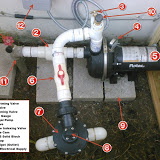
This is the most important part – it is the visual aid which I could not find anywhere online. Depicted below is my pump’s configuration. These are only the highlights, but I do have more pictures located in my picasa web album. The pictures are large, I did that on purpose for detail.
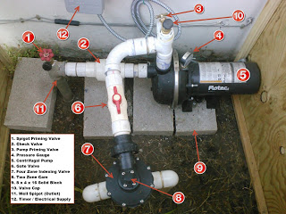 |
| System break down |
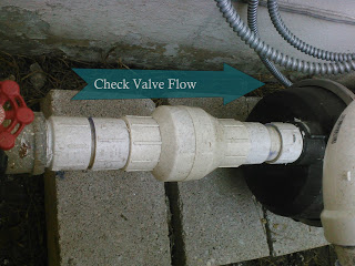 |
| Make sure that check valve is going in the right direction |
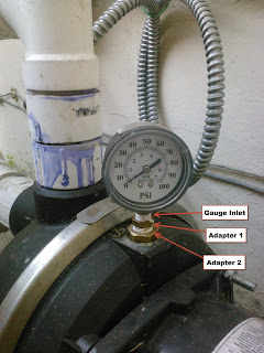 |
| Pressure gauge with 2 adapters to make it work. |
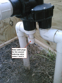 |
| Make shift plugs for the unused zones |
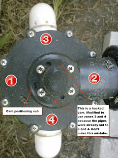 |
Showing my screw up with the indexing
valve configuration and the zone cams |
Related